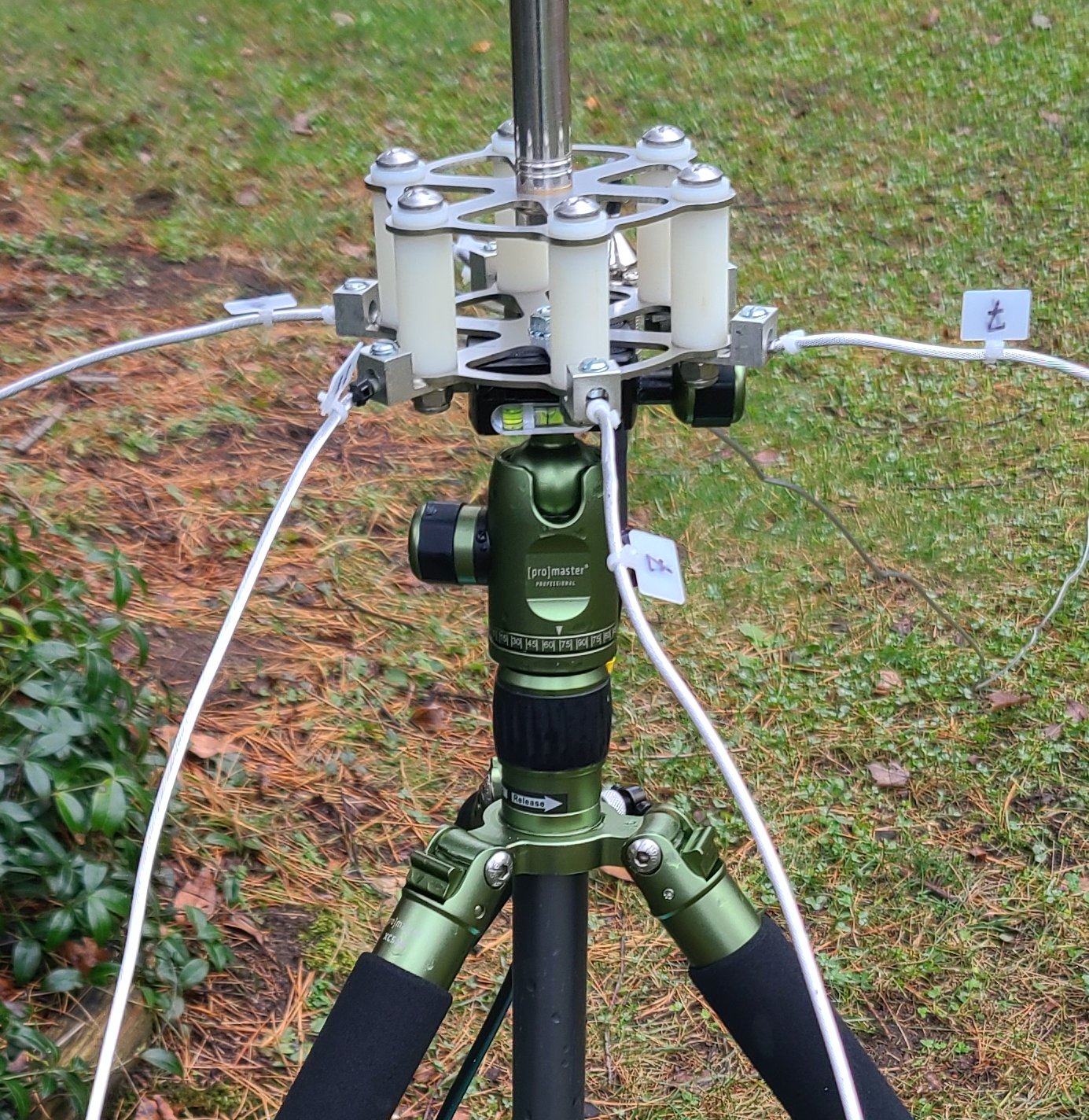
An auto-tuner friendly portable vertical antenna.
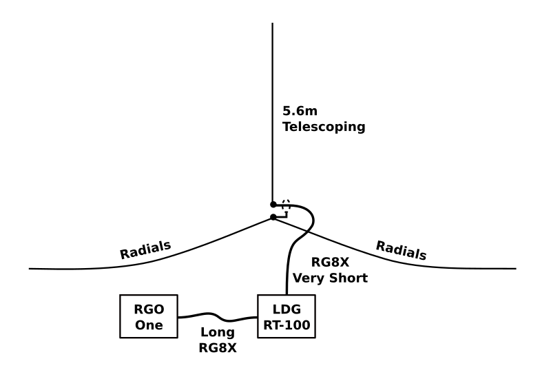
A homebrew vertical for mounting atop either a camera tripod or Spiderbeam mast. Designed to work with an LDG RT-100 remote auto-tuner.
While my rig (a Mission RGO One) has an ATU built-in, it is preferable instead to tune out SWR at the feedline’s far end. Hence my purchase of an LDG RT-100.
Having been taught by experience not to rely on any unit’s advertised SWR tuning range, I inquired prior to purchase about the RT-100’s internal components. See comparison table below.
| μHmin | μHmax | pFmin | pFmax | |
|---|---|---|---|---|
| Mission RGO One | 0.05 | 8.42 | 10 | 2531 |
| LDG RT-100 | 0.11 | 10.17 | 10 | 1270 |
| ATU-100 | 0.05 | 8.42 | 10 | 1869 |
As you will note, the RT-100’s range is less than either my RGO One or the ubiquitous ATU-100 which can be got very cheap. But I was needing a outdoor unit, so it was decided.
With AN-SOF 9.5 as my antenna modeling platform, that sofware’s Tuning tab, when set to low-pass L network, range values from the middle row above serve as go/no-go constraints.
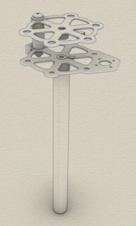
My hardware design is an adaptor for mounting a metric thread, 5.6m telescopic whip atop an imperial thread camera tripod. It has six 10AWG screw lugs as mount points to accomodate a goodly number of radials. Laser-cut 316 stainless, mine looks deceptively store-bought because, why not?
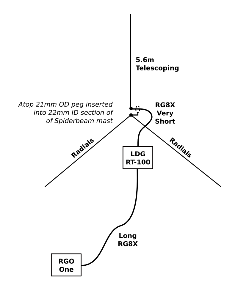
Then as an afterthought, I further designed an add-on bottom peg. This so as to optionally employ a Spiderbeam mast in place of said tripod, with radials running down along Dacron guys.
Below are illustrated both mounting options.
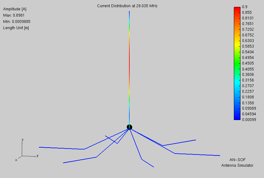
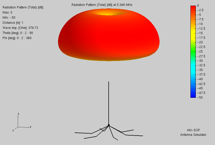
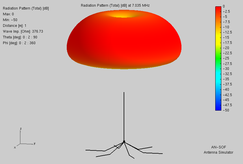
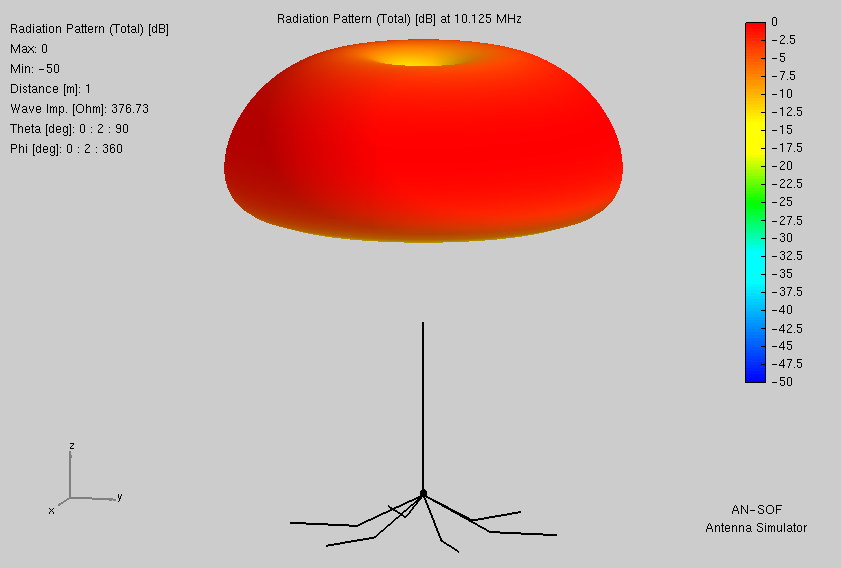
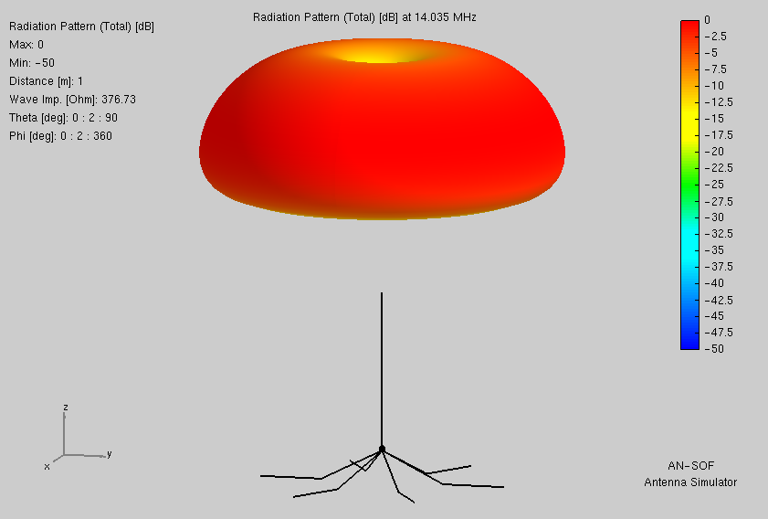
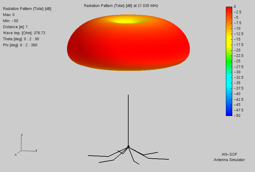
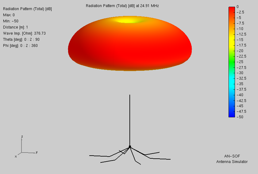
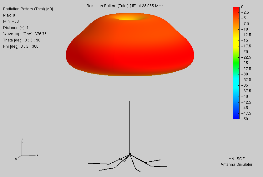
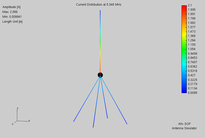
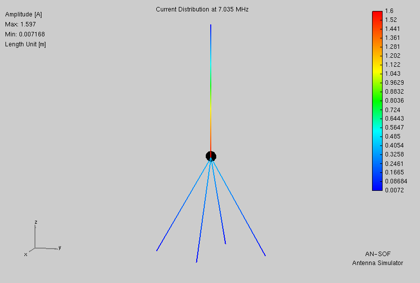
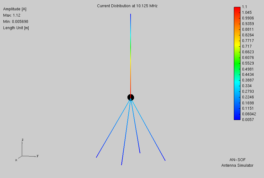
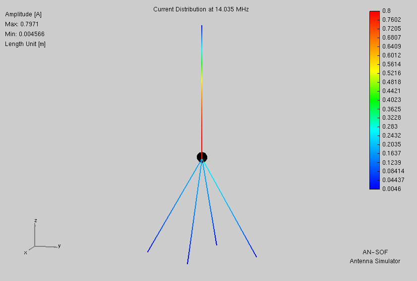
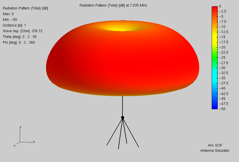
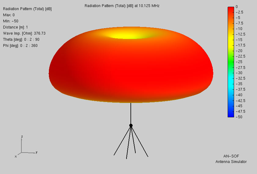
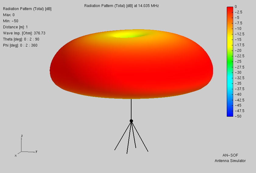
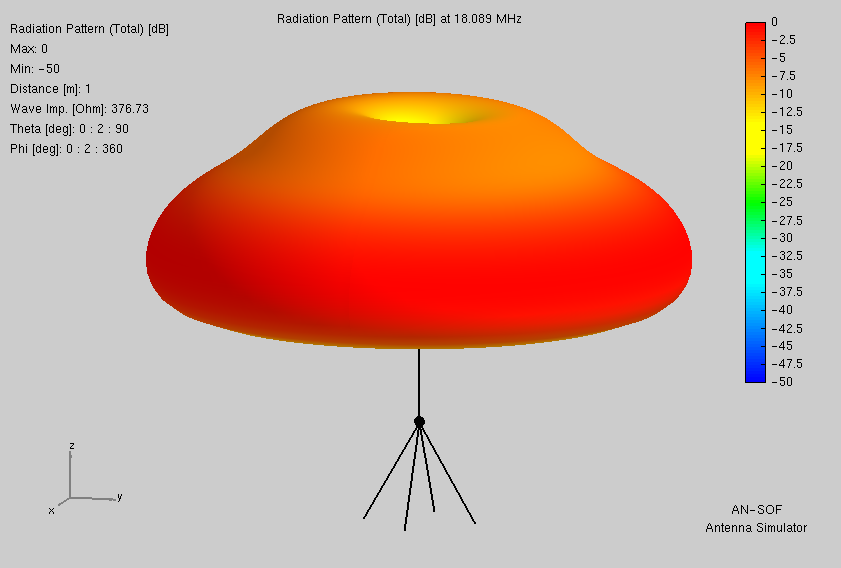
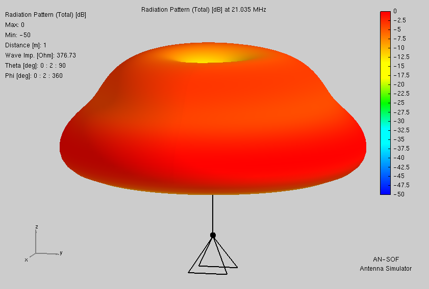
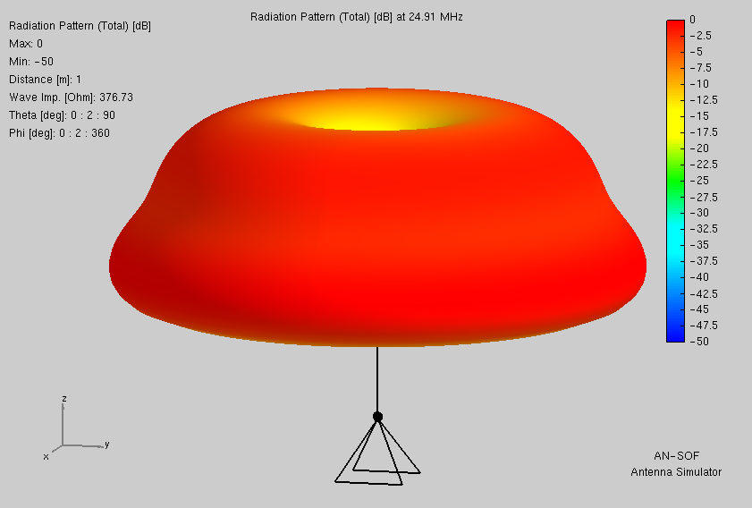
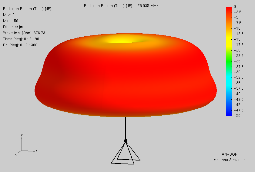
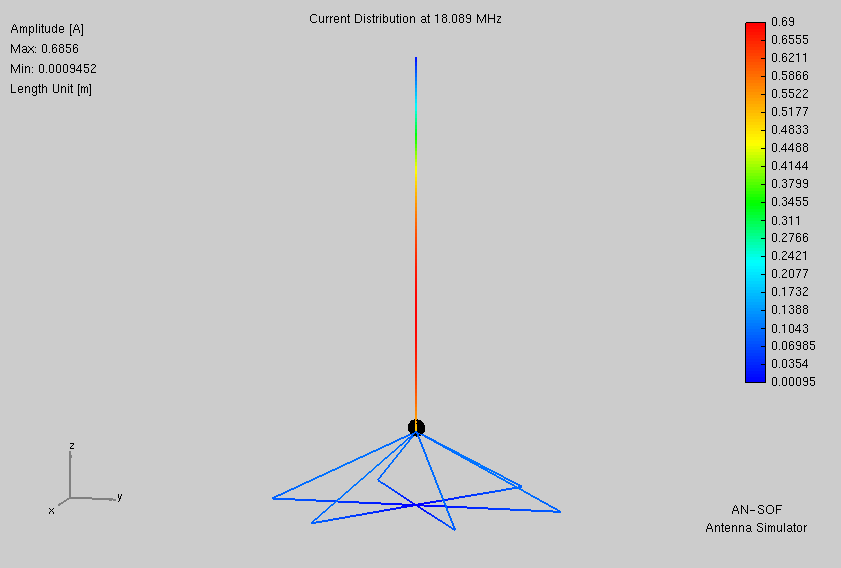
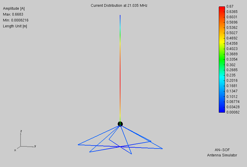
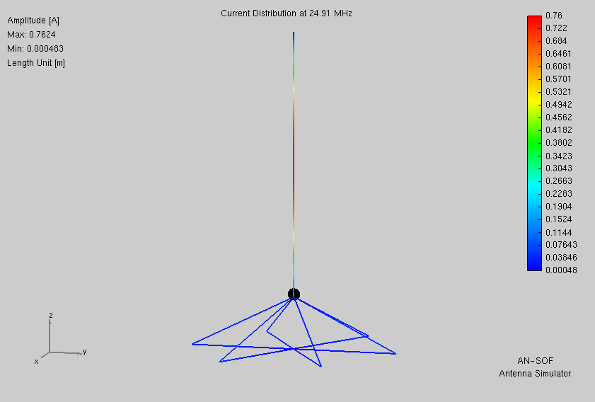
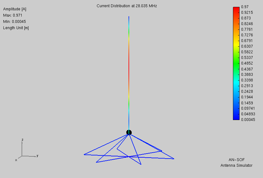
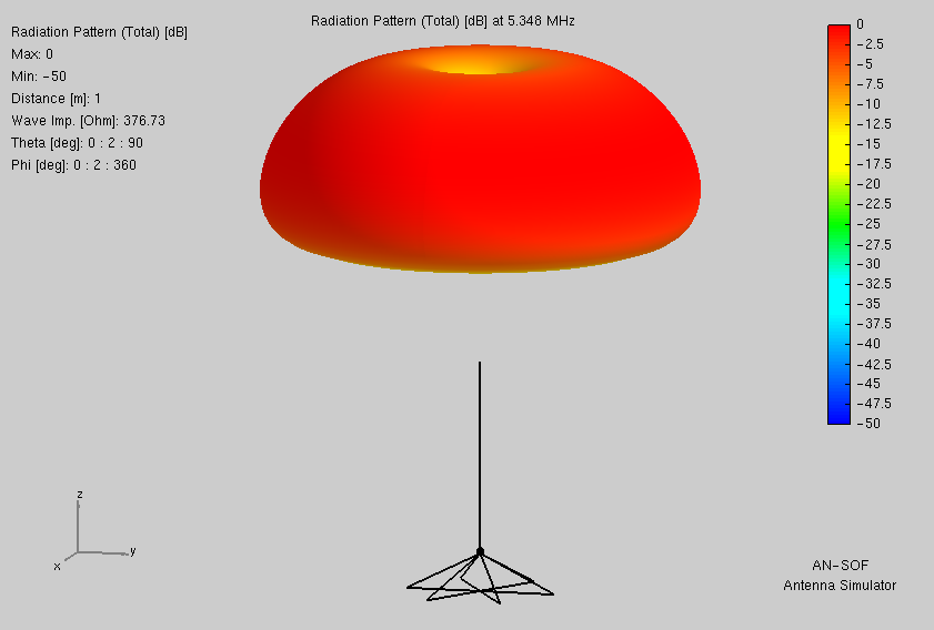
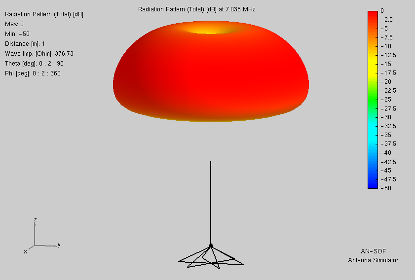
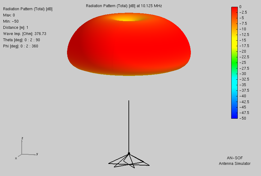
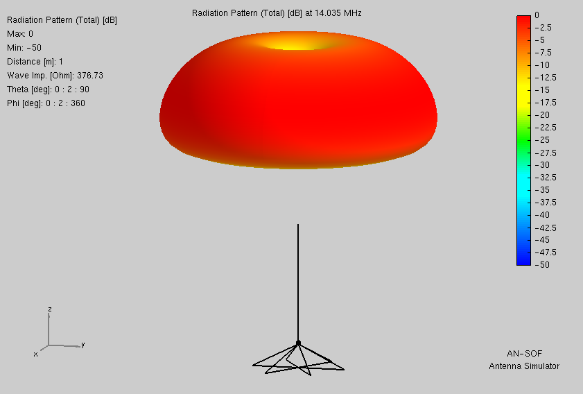
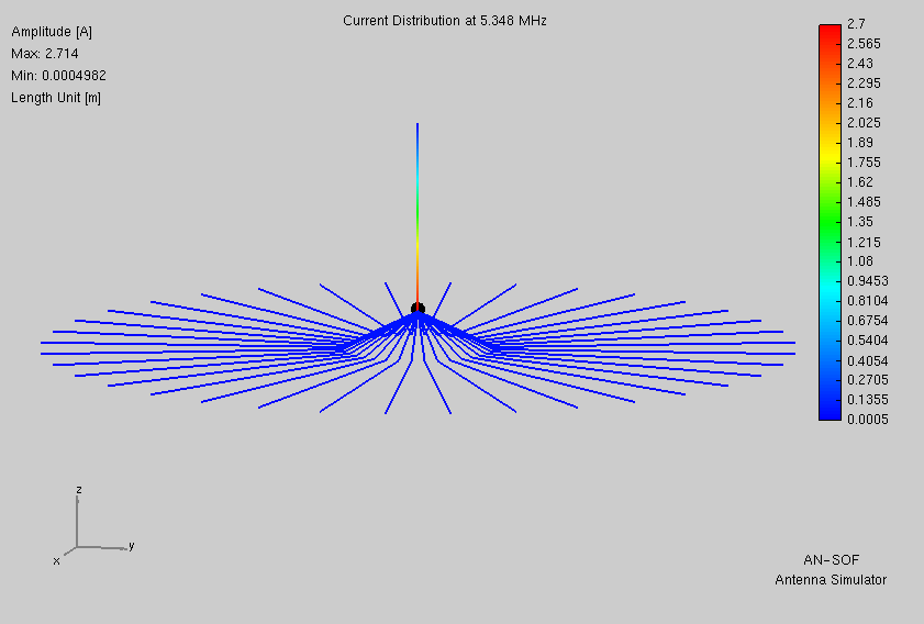
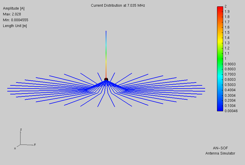
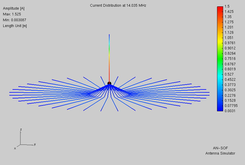
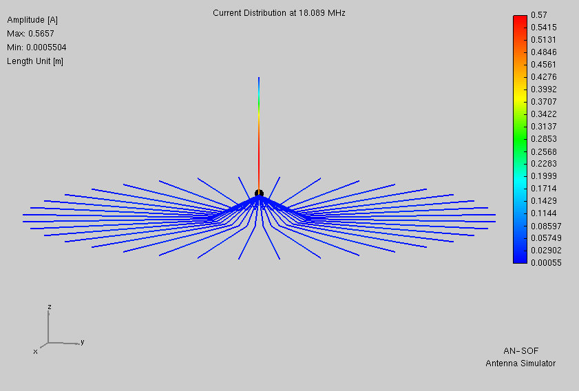
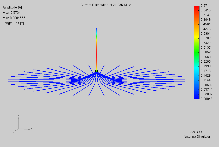
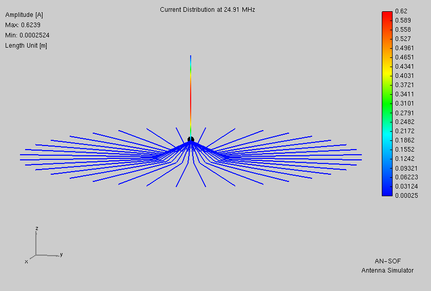
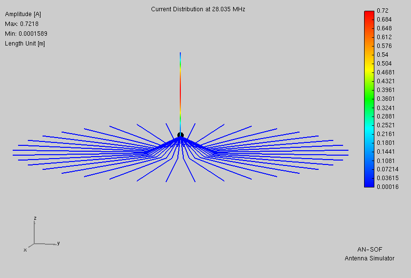
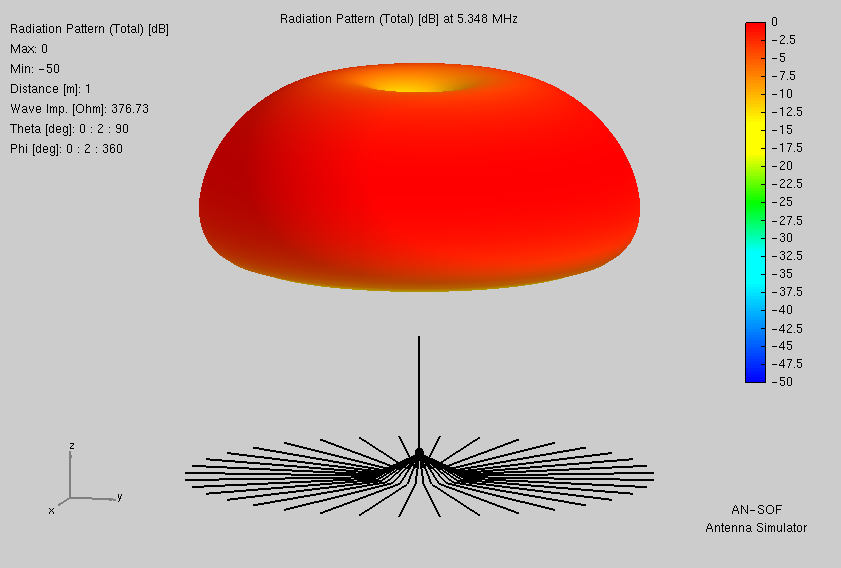
From atop a 1.1m tall camera tripod, six non-resonant radials drape down to fan out in the usual fashion.
This and all subsequent models employ a ‘real world’ ground simulating my destination of South Africa (dry, sandy, coastal).
Notably absent is a terminal ring wire. Thus the model’s presumption of a perfectly equal division of radial current (e.g. 360° radiation symmetry) is not likely realistic. More on this issue later.
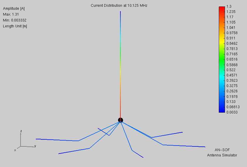
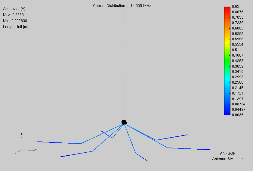
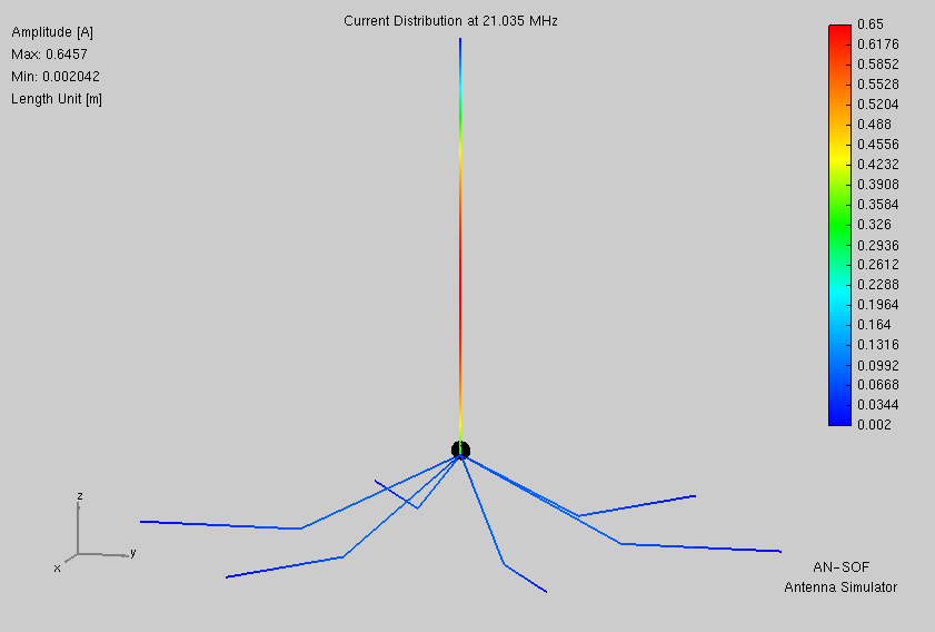
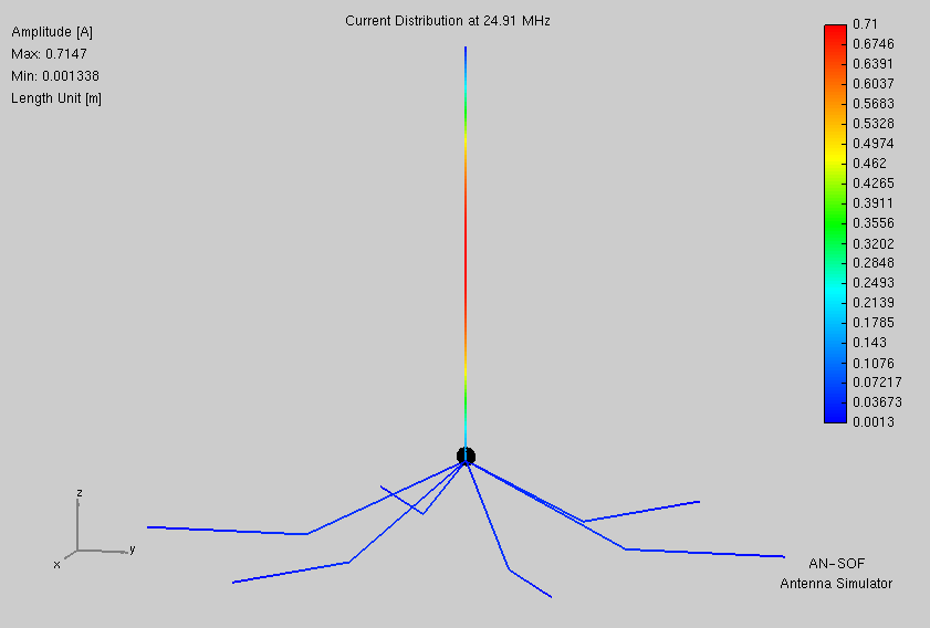
Here are the most pertinent data from AN-SOF. I do not list gain, but rather instead those two factors upon which gain is wholly dependent.
| 60m | 40m | 30m | 20m | 17m | 15m | 12m | 10m | |
|---|---|---|---|---|---|---|---|---|
| Directivity (dB) | 5.03 | 5.06 | 5.12 | 5.27 | 5.54 | 5.83 | 6.21 | 5.89 |
| Efficiency (%) | 27.0 | 26.7 | 26.5 | 26.3 | 26.5 | 27.1 | 29.3 | 34.8 |
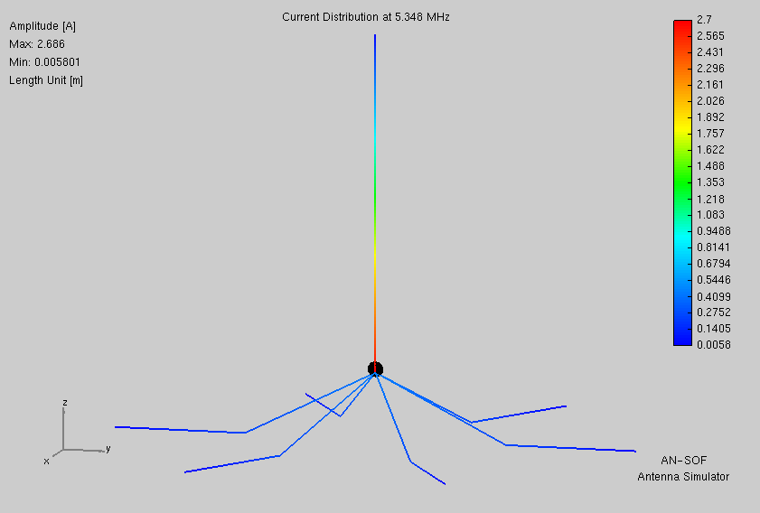
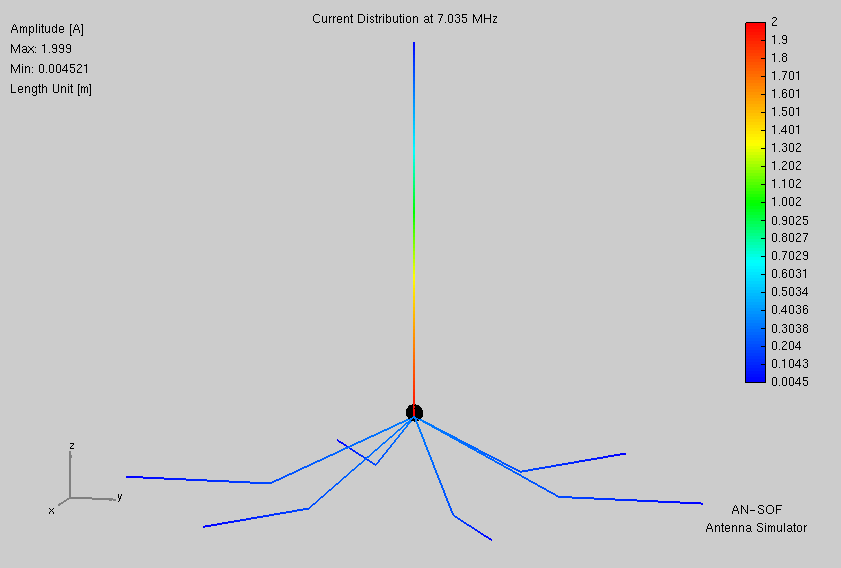
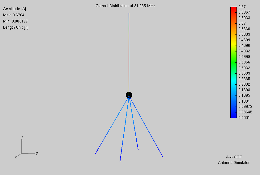
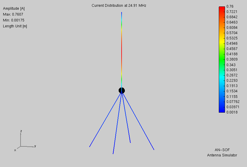
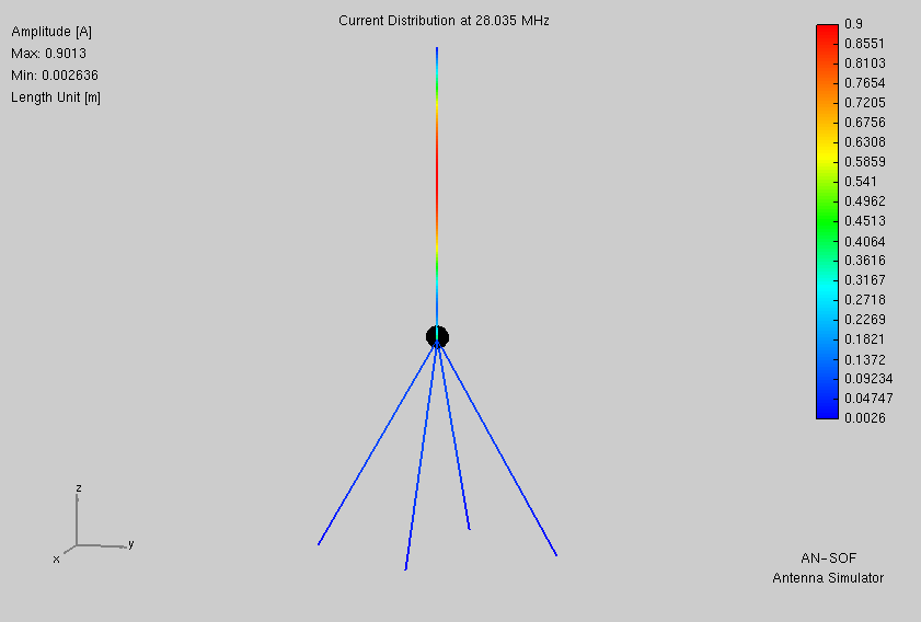
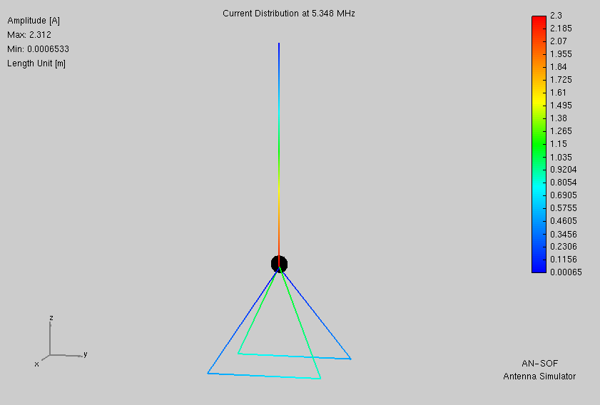
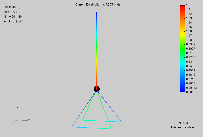
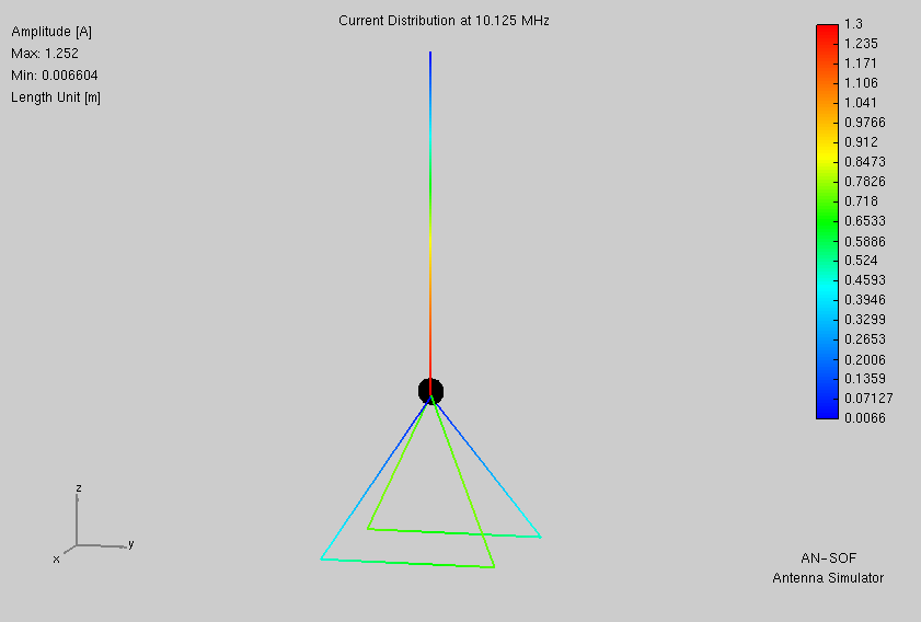
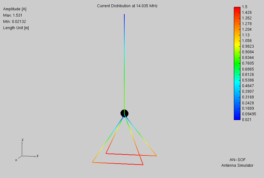
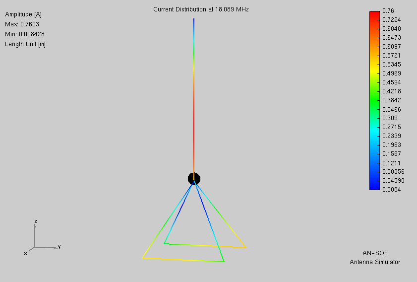
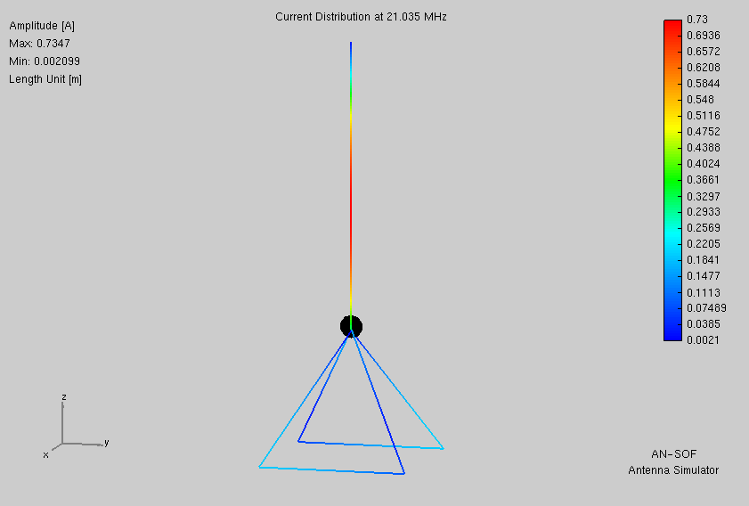
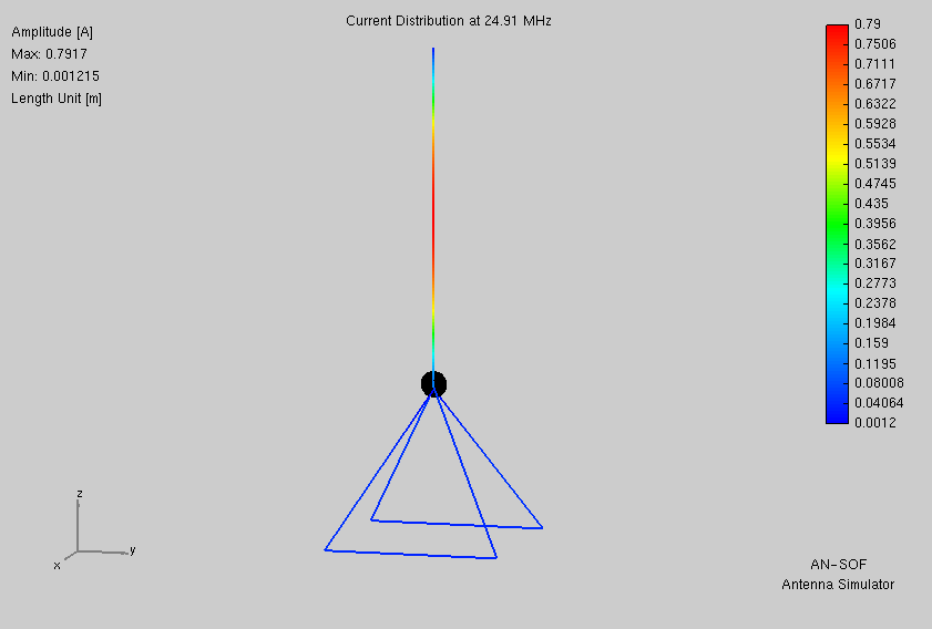
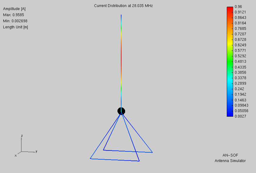
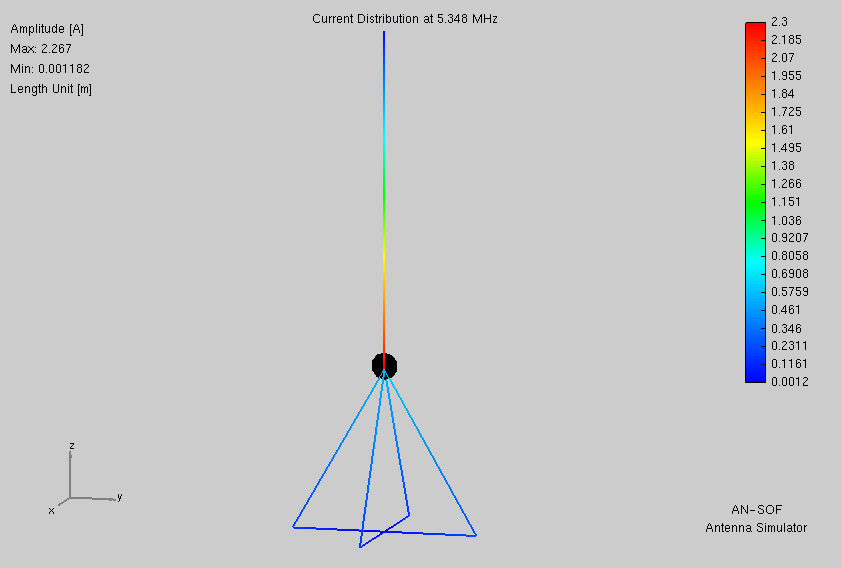
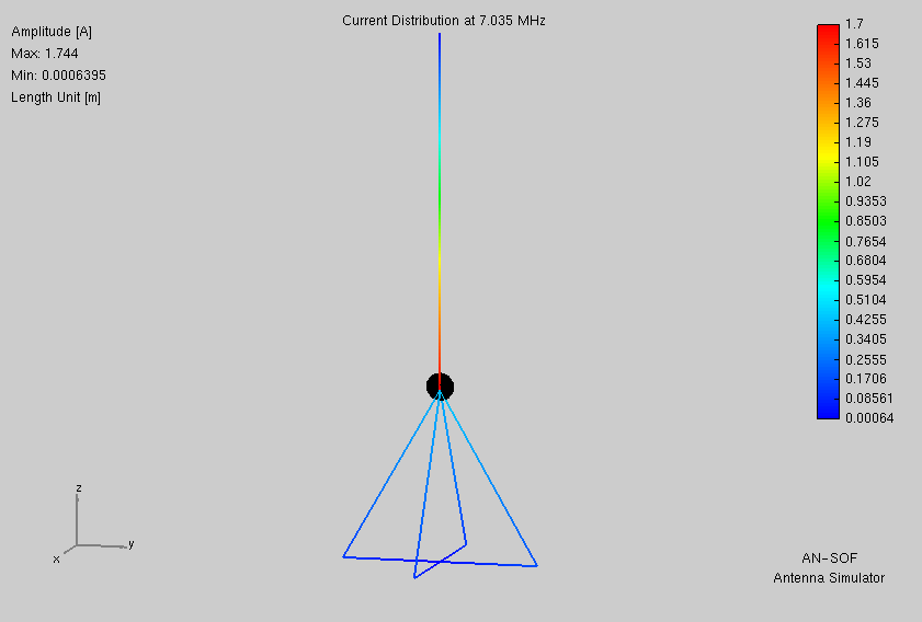
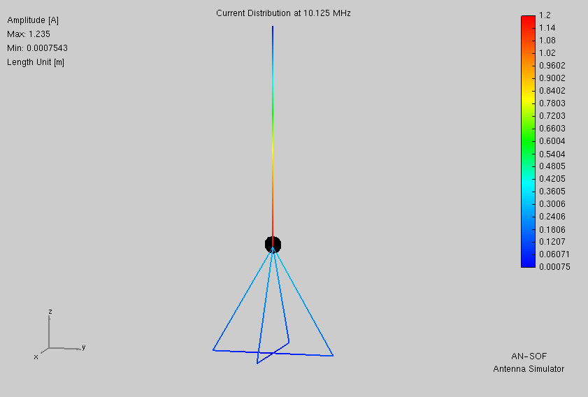
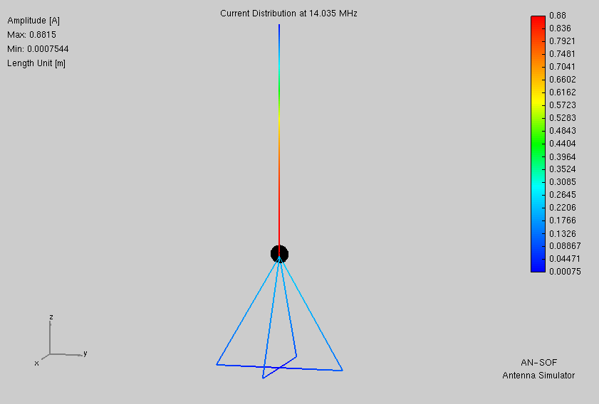
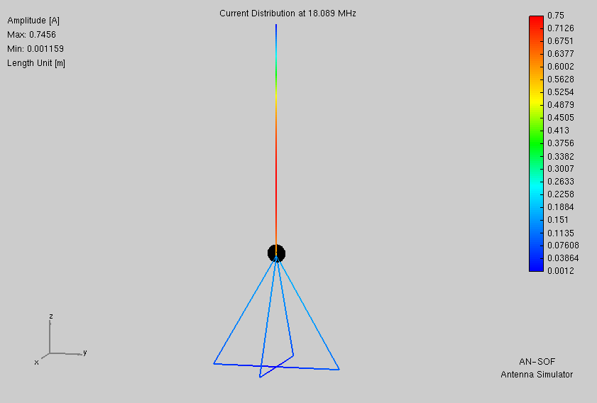
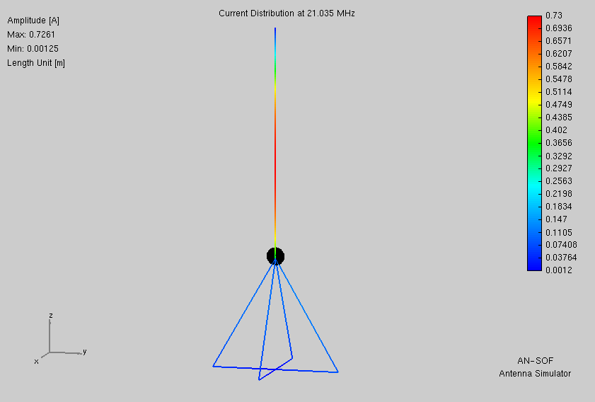
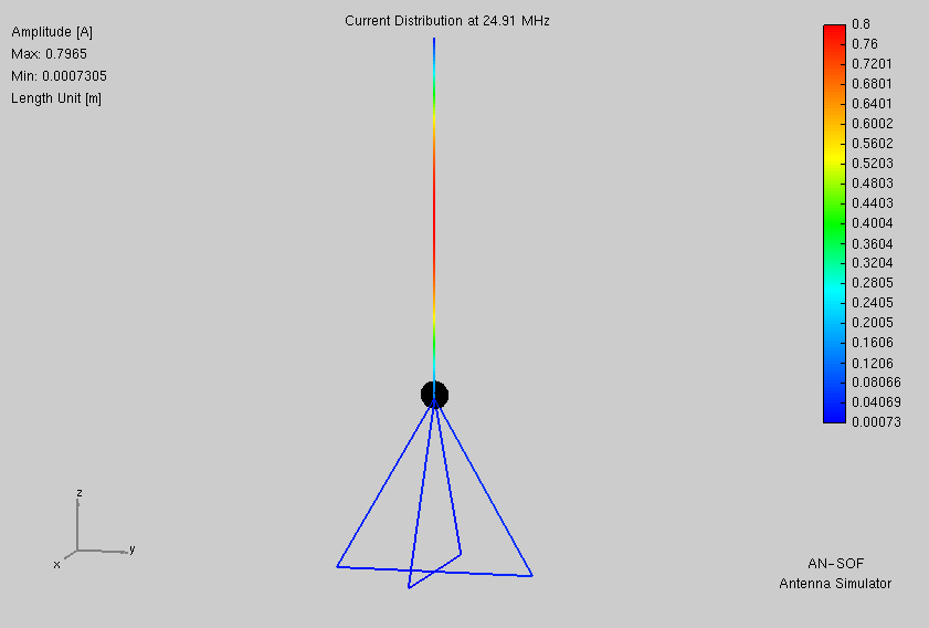
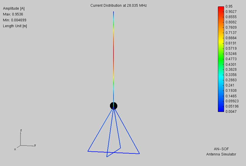
Here are current plots from AN-SOF.
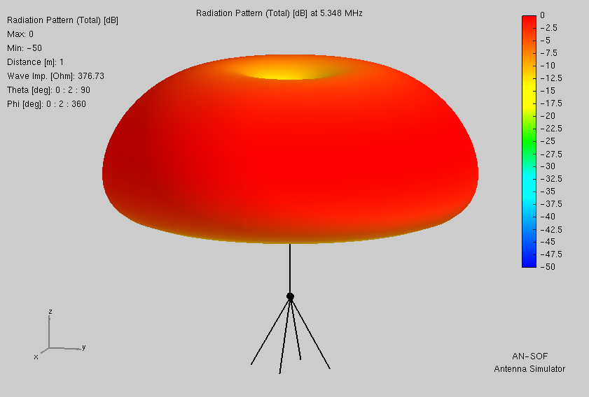
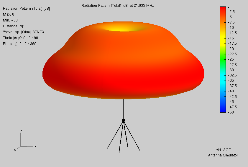
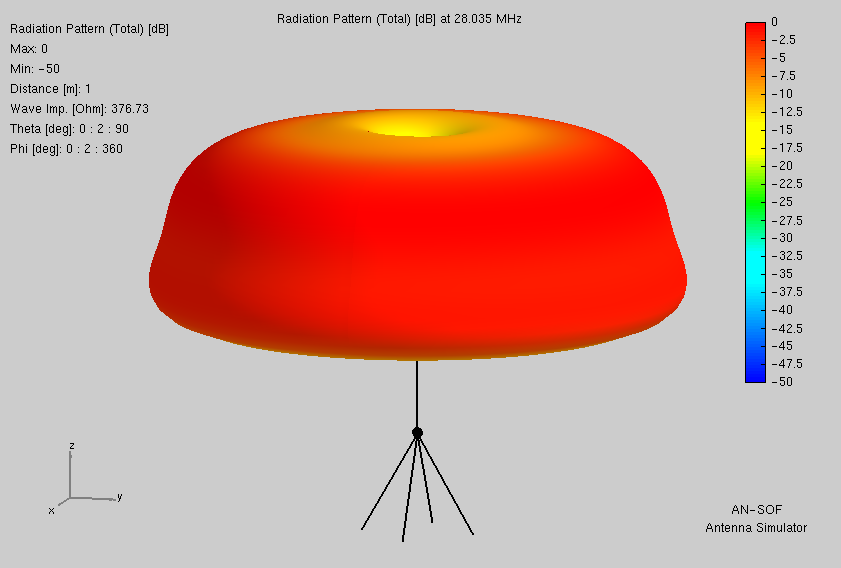
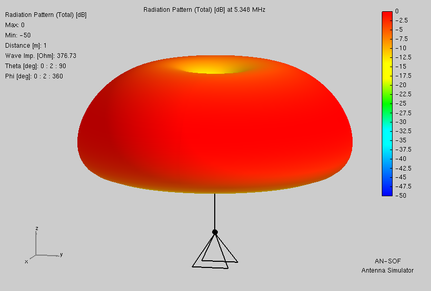
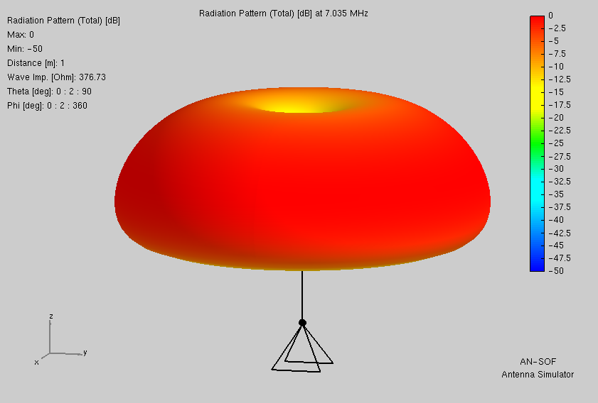
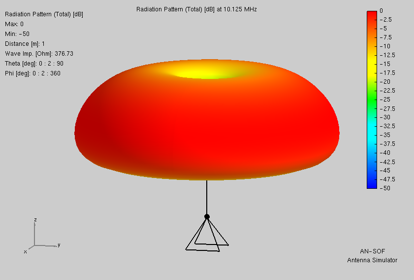
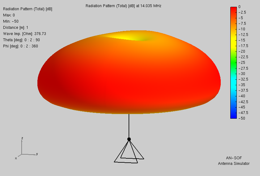
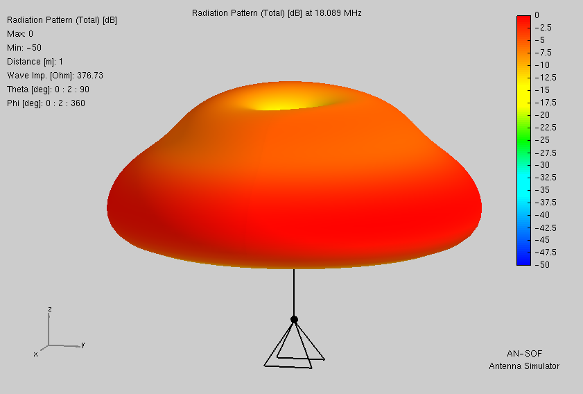
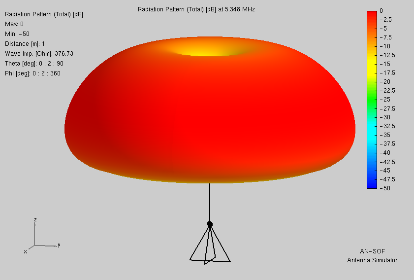
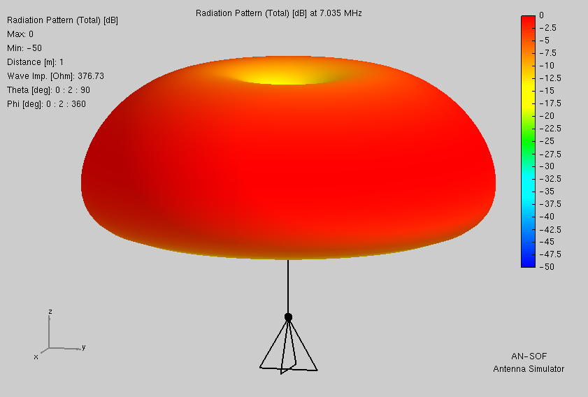
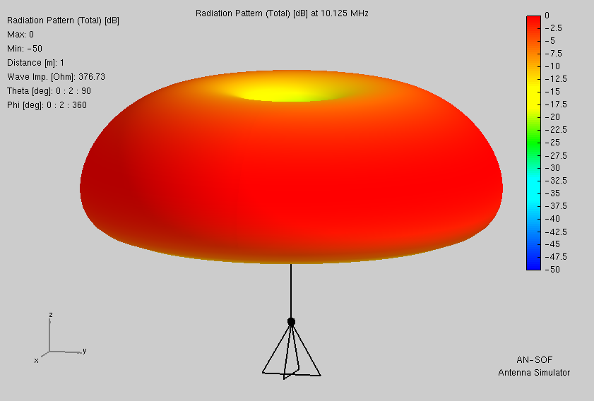
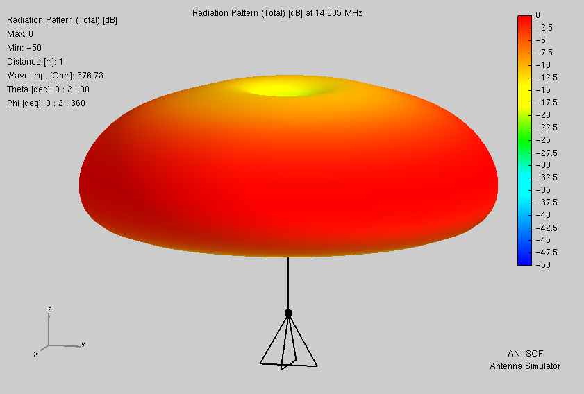
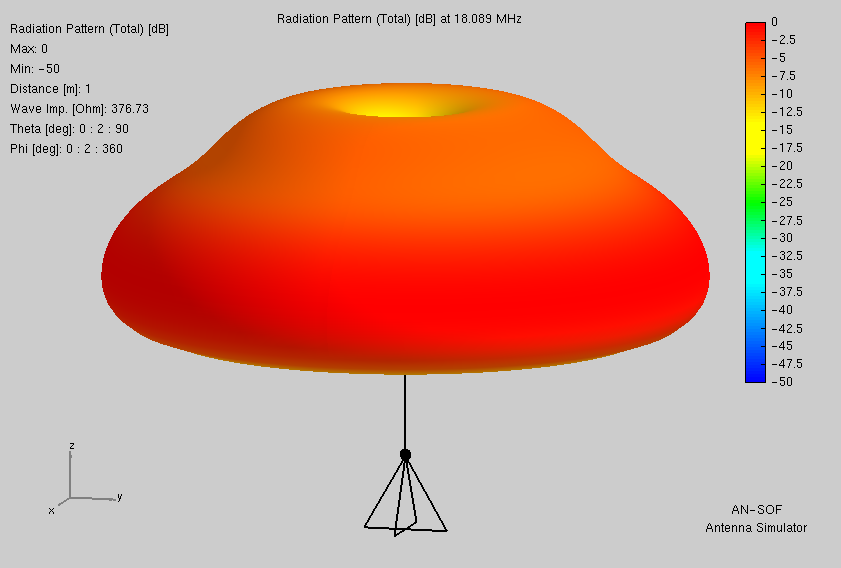
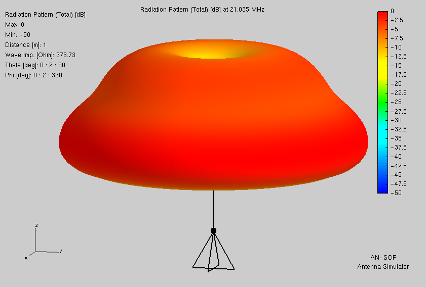
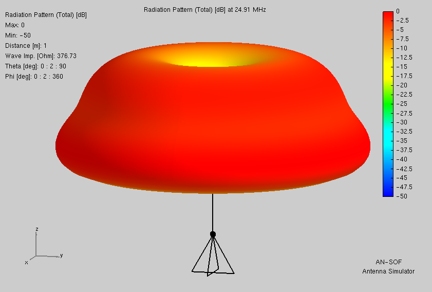
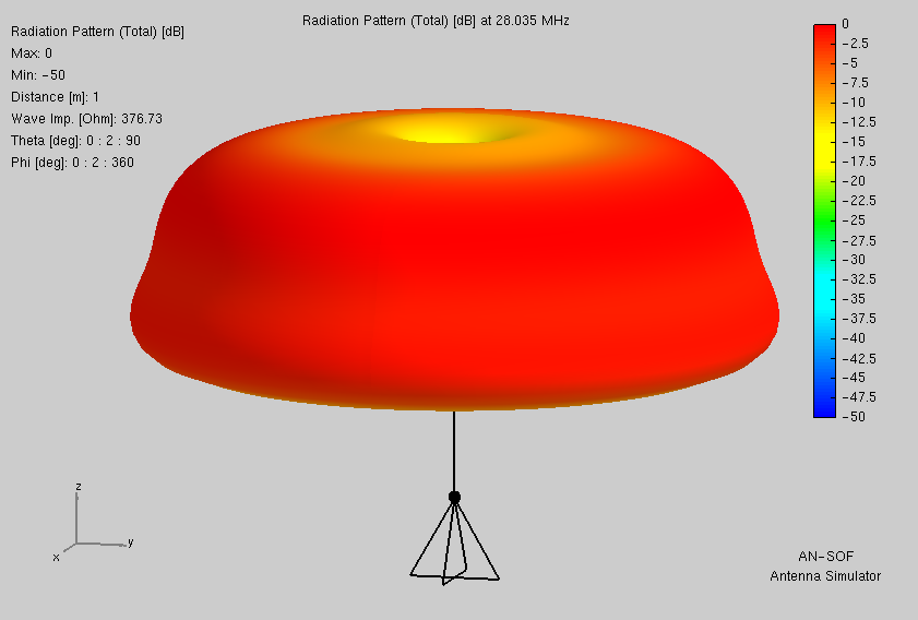
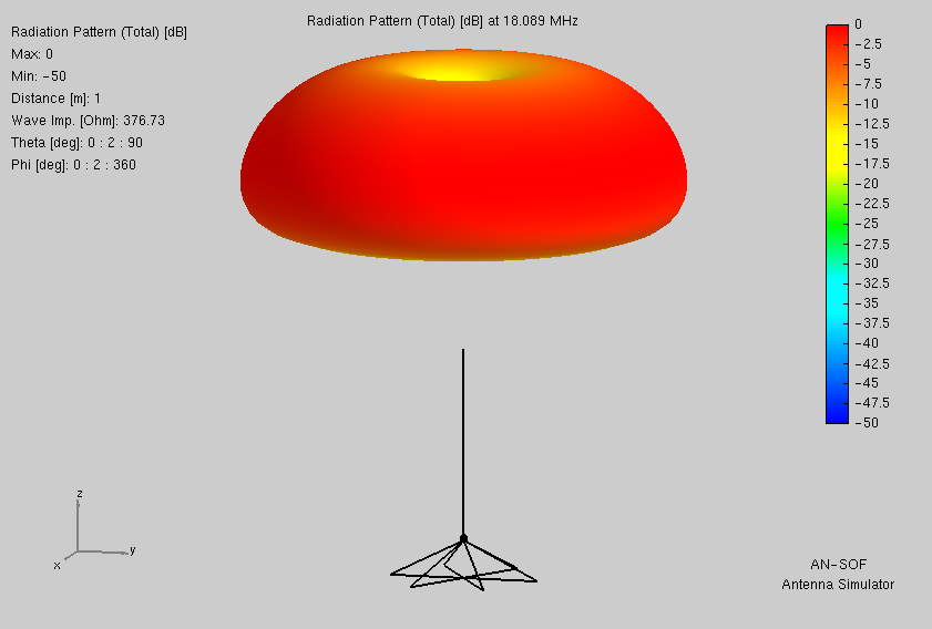
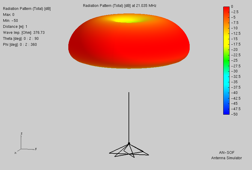
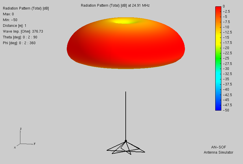
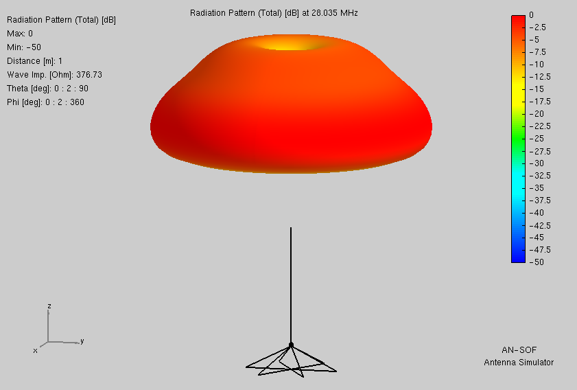
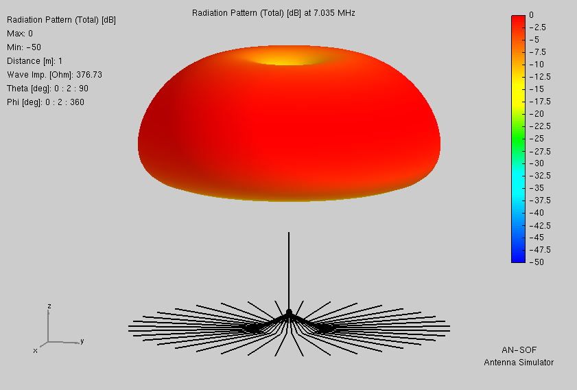
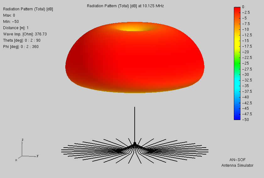
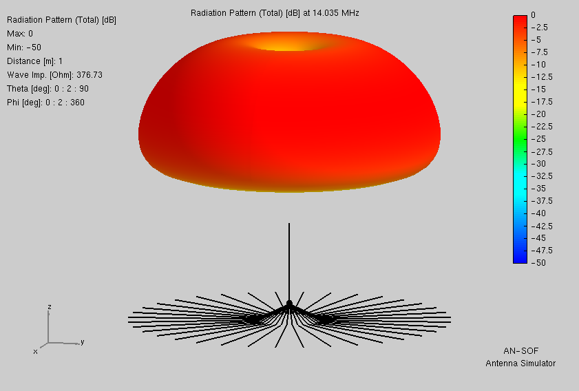
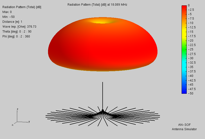
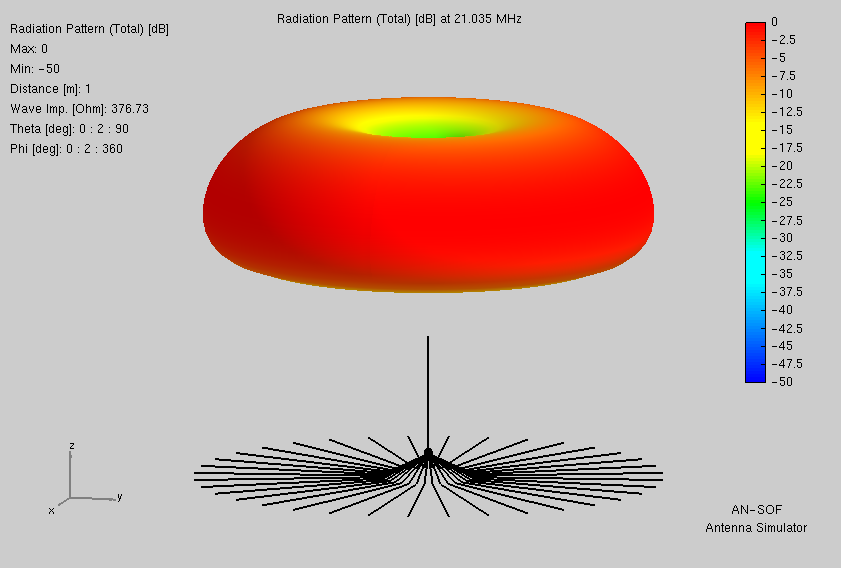
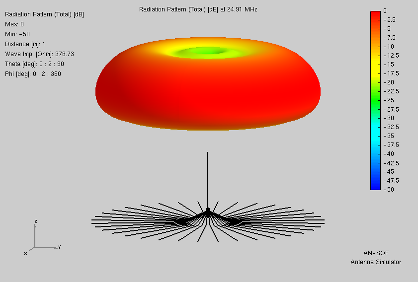
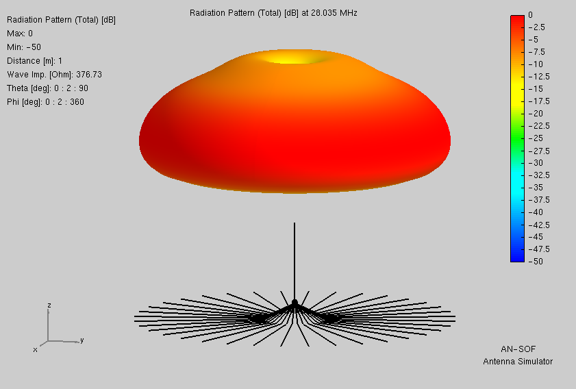
Here are the radiation patterns from AN-SOF.
Same hardware as above, but with the tripod replaced by a peg inserted into an upper section of Spiderbeam telescoping mast. Thus to raise the feedpoint from camera tripod height at 1.1m up to 5.75m on a 10m mast (7.85m if a 12m mast). But now with only four radials rather than six, these draping downward at 60° alongside Dacron suport guys. Model exported here: NEC
Here are the most pertinent data.
| 60m | 40m | 30m | 20m | 17m | 15m | 12m | 10m | |
|---|---|---|---|---|---|---|---|---|
| Directivity (dB) | 5.18 | 5.34 | 5.80 | 6.47 | 6.70 | 6.45 | 5.83 | 5.60 |
| Efficiency (%) | 25.8 | 25.4 | 25.1 | 26.3 | 30.7 | 35.1 | 46.6 | 64.1 |
Here are the current plots.
Here are the radiation patterns.
As evidenced from the prior two illustrations, my initial thought was to employ ordinary radials, as many and as long as I might hope to get away with.
Then (as always seems to happen) I found myself confronted by a compelling new concept. And here I refer you to a most informative QRZ page: JH1GNU .
I very recommend checking that out. Even right now, if you wish. I’ll be happy to wait… Okay then, moving on…
As JH1GNU so convincingly demonstrated, for radials to work properly each wire’s input impediance must present as exactly equal to every other. Identical length, alone by itself, in no way ensures this.
How broadcast stations ensure it is by first grooming the soil to maximum homogeneity. I have even read of their tilling in refined carbon (ref. ‘coke’). All before laying down hundreds of wires, and never failing to include a terminal ring wire.
Measures which park rangers would most likely frown upon. Short of those, what else might we aspire to do?
Elevating radials will, in theory, allow we get by with just only two. Said theory’s computer model, alas, falsely assumes something which nowhere exists: a perfectly homogenous environment, the total absence of any external detuning factors.
End result: an uneven division of current. Possibly even to such a degree as functions instead more like a dipole, one leg of which runs horizontal and close to the ground.
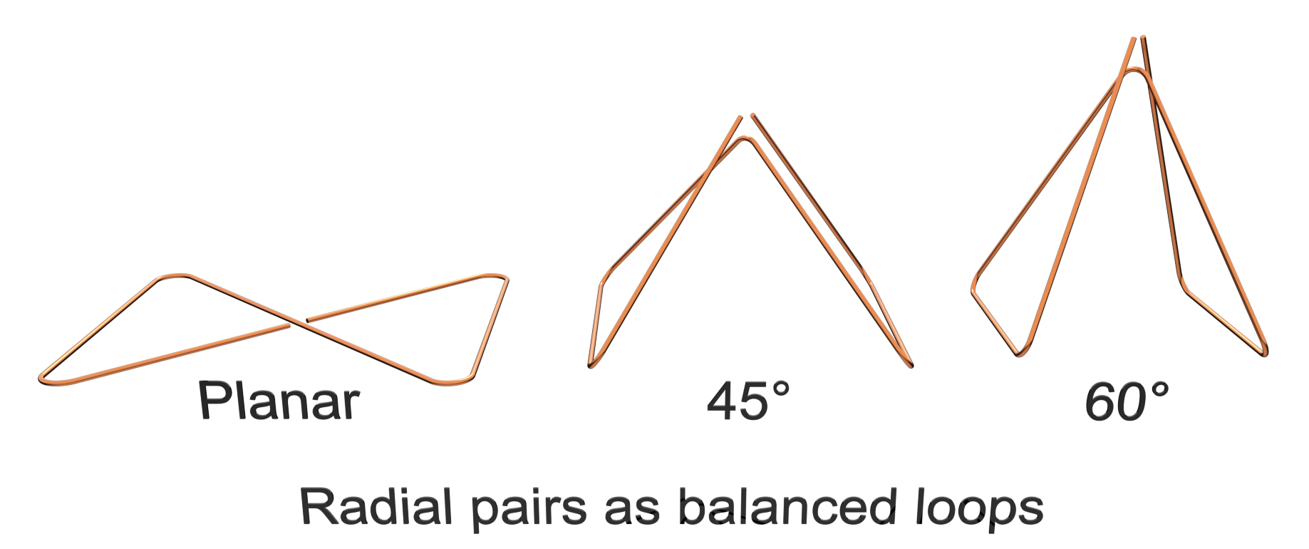
If however (as JH1GNU describes), one loops the radial end points back toward one another so as to meet at the center … this without their touching anything else … the absent terminal ring wire’s function is hereby restored.
Let us compare. Below are models of various radial configurations, both ground-level and elevated. My elevated models employ 1/3 less total wire than do my ground-level models. The reason is practicality: six is easy to do on the ground, but a mast has only four guys.
Butterfly is my own private term, employed here to differentiate from Delta discussed further down. One third less wire is employed than for the traditional fan-out arrangement above. Said wire is configured as a variation upon the planar loop design promoted by JH1GNU. I have folded its two halves downward so as to conveniently follow Dacron suport guys staked at 60°. Model exported here: NEC
|
|
Here are the most pertinent data.
| 60m | 40m | 30m | 20m | 17m | 15m | 12m | 10m | |
|---|---|---|---|---|---|---|---|---|
| Directivity (dB) | 5.22 | 5.42 | 5.99 | 6.89 | 6.60 | 6.10 | 5.52 | 5.53 |
| Efficiency (%) | 25.6 | 27.2 | 25.0 | 28.3 | 36.4 | 41.3 | 50.4 | 63.2 |
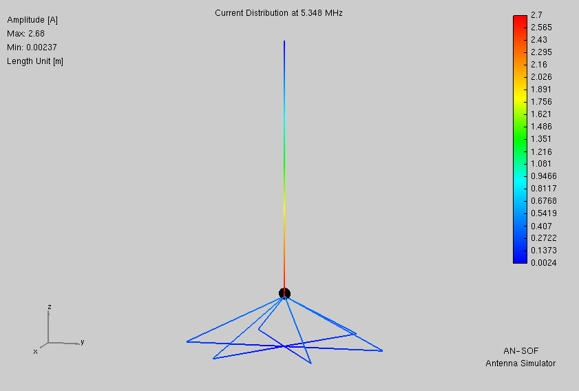
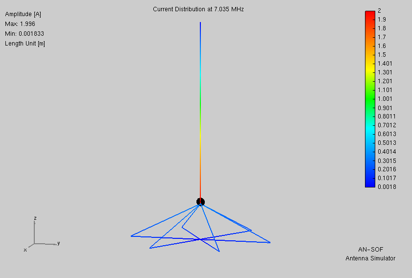
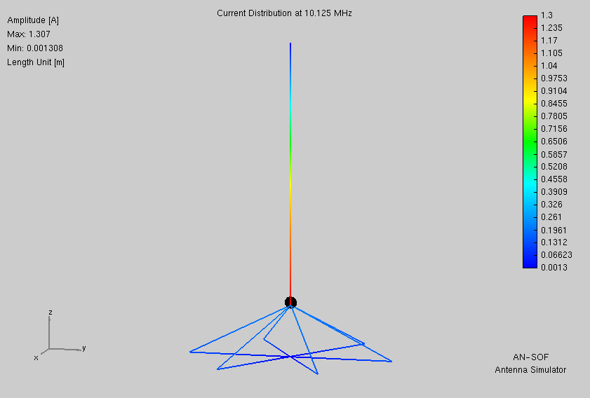
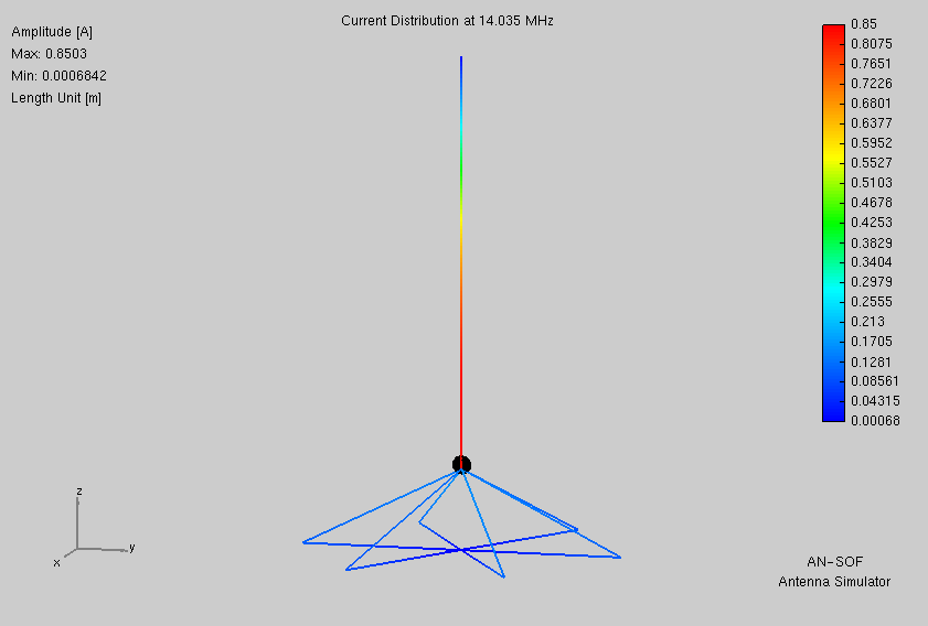
Here are the current plots.
Here are the radiation patterns.
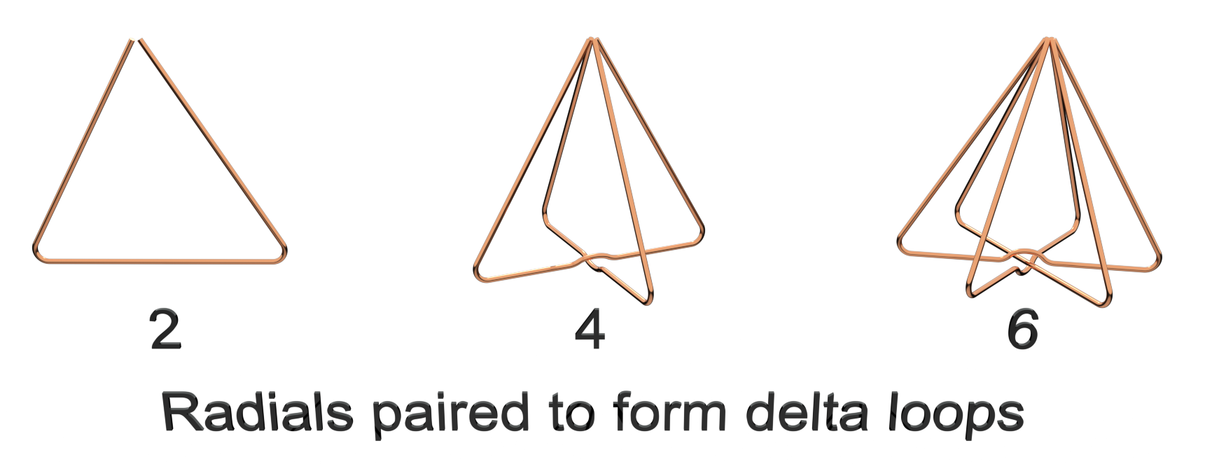
Again my own term, so as to differentiate from Butterfly above. An idea which just popped into my head. The same length of wire, but here configured as four radials rather than two. Those grouped as two pair, each pair forming a vertical delta, with radial ends meeting instead at the base. Considered as wire frame structures, Butterfly and Delta each encompass nearly identical pyramidal volumes. Delta, as I call it here, forms something of a skeleton conical ground plane. Model exported here: NEC
|
|
Pertinent data.
| 60m | 40m | 30m | 20m | 17m | 15m | 12m | 10m | |
|---|---|---|---|---|---|---|---|---|
| Directivity (dB) | 5.18 | 5.36 | 5.83 | 6.41 | 6.45 | 6.10 | 5.48 | 5.71 |
| Efficiency (%) | 25.4 | 25.0 | 24.8 | 26.5 | 31.9 | 37.8 | 46.9 | 57.9 |
Current plots.
Radiation patterns.
So then I wondered, what if I lowered the delta radial arrangement down from its perch atop the Spiderbeam mast onto the camera tripod? For this the delta needed to be broadened and flattend a bit. Enough, anyhow so to fit under the tripod. That plus an increase from four radials at 90° to six at 60° made for symmetry amid the tripod’s three legs. Model exported here: NEC
Pertinent data.
| 60m | 40m | 30m | 20m | 17m | 15m | 12m | 10m | |
|---|---|---|---|---|---|---|---|---|
| Directivity (dB) | 5.03 | 5.06 | 5.13 | 5.29 | 5.59 | 5.91 | 6.34 | 5.89 |
| Efficiency (%) | 26.9 | 26.7 | 26.4 | 26.2 | 26.2 | 26.6 | 29.9 | 42.0 |
Current plots.
Radiation patterns.
I had thought to likewise attempt lowering butterfly radials in a similar manner. But no such model met with success. In every case, AN-SOF’s Tuning tab predicted low-pass L network capacitance requirements far outside the range of an LDG RT-100.
Scrolling up-page tells why. Compare the current plots: Elevated Butterfly versus Elevated Delta. What colors show in the horizontal wires at very bottom? For Delta, always an icy deep blue. For Butterfly on the other hand... Okay, so bad idea. What was I thinking? Moving on...
For all the above, we are needing a control example against which to compare. Therefor I now model according to the dictum that more and longer radials are always better. What might I hope to acheive, were I less frugal, impatient, and lazy? Model exported here: NEC
Pertinent data.
| 60m | 40m | 30m | 20m | 17m | 15m | 12m | 10m | |
|---|---|---|---|---|---|---|---|---|
| Directivity (dB) | 5.90 | 5.05 | 5.09 | 5.49 | 5.45 | 6.22 | 6.50 | 6.40 |
| Efficiency (%) | 27.7 | 29.9 | 35.4 | 27.4 | 14.4 | 17.9 | 24.9 | 32.9 |
Current plots.
Radiation patterns.
Here I aggregate stats from all cases above that we may compare.
Directivities (dB)
| 60m | 40m | 30m | 20m | 17m | 15m | 12m | 10m | |
|---|---|---|---|---|---|---|---|---|
| Tripod Mount (6) | 5.03 | 5.06 | 5.12 | 5.27 | 5.54 | 5.83 | 6.21 | 5.89 |
| Mast Mount (4) | 5.18 | 5.34 | 5.80 | 6.47 | 6.70 | 6.45 | 5.83 | 5.60 |
| Elevated Butterfly (2) | 5.22 | 5.42 | 5.99 | 6.89 | 6.60 | 6.10 | 5.52 | 5.53 |
| Elevated Delta (4) | 5.18 | 5.36 | 5.83 | 6.41 | 6.45 | 6.10 | 5.48 | 5.71 |
| Ground Level Delta (6) | 5.03 | 5.06 | 5.13 | 5.29 | 5.59 | 5.91 | 6.34 | 5.89 |
| Ground Level Classic (36) | 5.90 | 5.05 | 5.09 | 5.49 | 5.45 | 6.22 | 6.50 | 6.40 |
Efficiencies (%)
| 60m | 40m | 30m | 20m | 17m | 15m | 12m | 10m | |
|---|---|---|---|---|---|---|---|---|
| Tripod Mount (6) | 27.0 | 26.7 | 26.5 | 26.3 | 26.5 | 27.1 | 29.3 | 34.8 |
| Mast Mount (4) | 25.8 | 25.4 | 25.1 | 26.3 | 30.7 | 35.1 | 46.6 | 64.1 |
| Elevated Butterfly (2) | 25.6 | 27.2 | 25.0 | 28.3 | 36.4 | 41.3 | 50.4 | 63.2 |
| Elevated Delta (4) | 25.4 | 25.0 | 24.8 | 26.5 | 31.9 | 37.8 | 46.9 | 57.9 |
| Ground Level Delta (6) | 26.9 | 26.7 | 26.4 | 26.2 | 26.2 | 26.6 | 29.9 | 42.0 |
| Ground Level Classic (36) | 27.7 | 29.9 | 35.4 | 27.4 | 14.4 | 17.9 | 24.9 | 32.9 |
It seems I have put myself to a great deal of effort simply to vindicate JH1GNU’s prior assertion: a single pair of elevated radials, joined end-to-end as a figure-8 loop, is both highly effective and sufficient.
Noteworthy however are results also for Ground Level Delta (6), as they indicate how I can greatly reduce a vertical antenna’s footprint in public spaces where elevation is not practical. Park rangers will surely approve!
Two plates are laser cut from 18GA stainless. All other parts are from McMaster-Carr.
Whip and radials assembly:
Peg extension for Spiderbeam mast
While I haven’t yet boarded the plane for Cape Town, still I consider the basic concept proven by virtue of testing in the side-yard at my home QTH (peformed prior discovery of the new radials concept). My newly acquired LDG RT-100 proved able to tune the antenna from 10m through 60m. This while configured with an ad hoc arrangement of six non-resonant radials (one pair each of 11.348m, 7.580m, and 5.731m) draped loosely along the ground.
QSOs were obtained on all bands 10m through 60m, WARC included. These reports were obtained: 559 from VK2BJ on 10m, 579 from TI5/VA3RA on 12m, and 559 from CT9/UR9IDX on 17m. All QSOs were got as a camera-tripod mount with whip at full extension. No attempt has yet been made as a mast mount.
Latin for “Let the moocher beware”. I composed this for me, and employed it with glee. I share it here with you for free, but offered without even so much as the smell of a dead warranty (or wheriot, as the case may be). Whatsoever disasters of cosmic proportion as may result from the use of this information, any and all culpability rests wholly and solely with the user.
My contact email and postal address are on QRZ.com for call sign KY8D